Screenshots
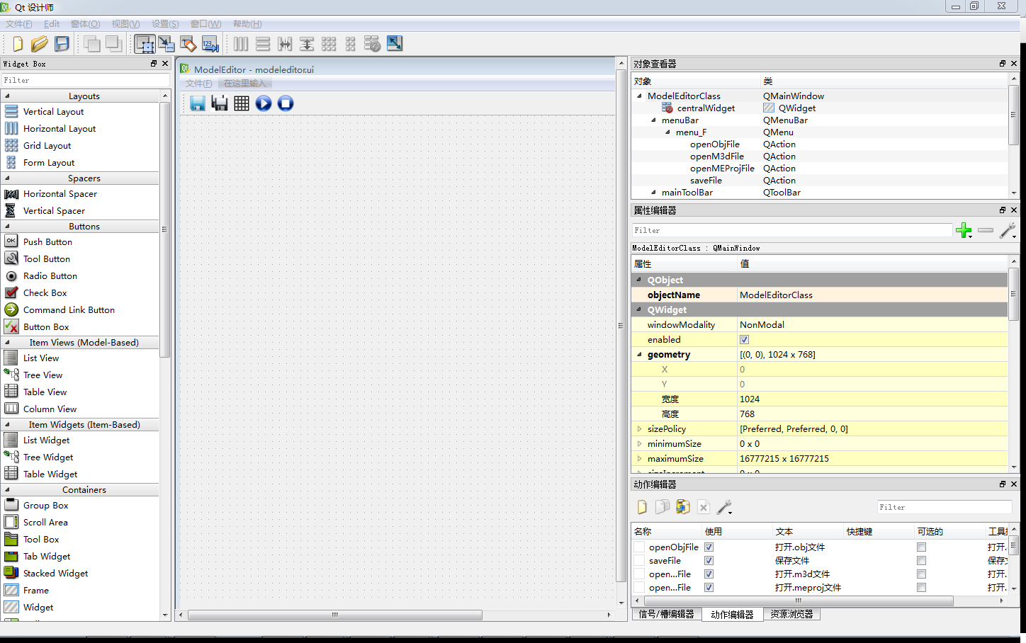
Qt Framework 
Qt (/ˈkjuːt/ “cute”, or unofficially as Q-T cue-tee) is a cross-platform application framework that is widely used for developing application software that can be run on various software and hardware platforms with little or no change in the underlying codebase, while still being a native application with the capabilities and speed thereof. Qt is currently being developed both by the Qt Company, a subsidiary of Digia, and the Qt Project under open-source governance, involving individual developers and firms working to advance Qt. Digia owns the Qt trademark and copyright. Qt is available with both commercial and open source GPL v3, LGPL v3 and LGPL v2 licenses.
I chose Qt GUI instead of MFC for our project considering its feature of simple operation, good across-platform, powerful maintainability and expansibility.
DirectX11 Framework 
Microsoft DirectX is a collection of application programming interfaces (APIs) for handling tasks related to multimedia, especially game programming and video, on Microsoft platforms.
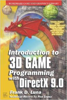
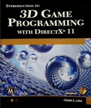
The book-Introduction to 3D Game Programming with Directx 11 introduces DirectX11 as well as basic graphics knowledge to readers. The author also wrote Introduction to 3D Game Programming with DirectX 9.0, which is also a classical teaching material of DirectX9.0. However, the fix-function pipeline in DirectX9.0 is outmoded and the programmable pipeline in DirectX11 is prefered in the industry.
I implemented lots of effects using DirectX11.
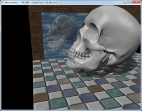
- Mirror & Shadow Mapping
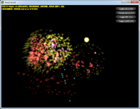
- Particle System
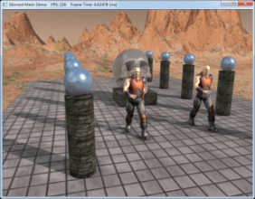
- Skybox & Animation & Normal Mapping
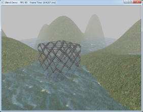
- Blending
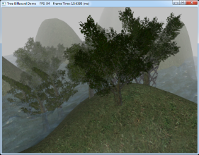
- Tree Billboard
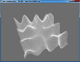
- Tessellation
Line Tool based on Qt and DirectX11
To enhance my proficiency in both Qt and DirectX11, I implemented a line tool.
OpenGL is supported well by Qt because they are both across-platform. However, DirectX is not supported officially by Qt. I encountered some difficulties in combining Qt and DirectX. Fortunately, the problem was solved. I disabled QPaintEngine provided by Qt and overwrote paintEvent as well as resizeEvent in order to enable DirectX11 to render onto the widget.
The core codes implementing the combination are showed as below.
virtual QPaintEngine* paintEngine() const { return NULL; }DxWidget::DxWidget() // DxWidget inherits from QWidget
{
setAttribute(Qt::WA_PaintOnScreen, true);
setAttribute(Qt::WA_NativeWindow, true);
...
}
void DxWidget::resizeEvent(QResizeEvent* pEvent)
{
DxRender();
}
void DxWidget::paintEvent(QPaintEvent* pEvent)
{
DxRender();
}Then the program runs well.
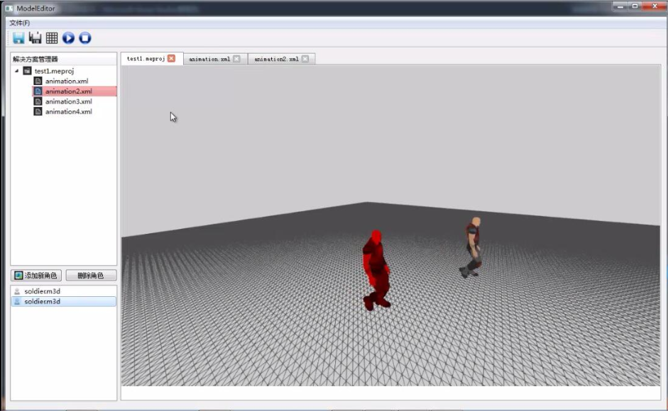
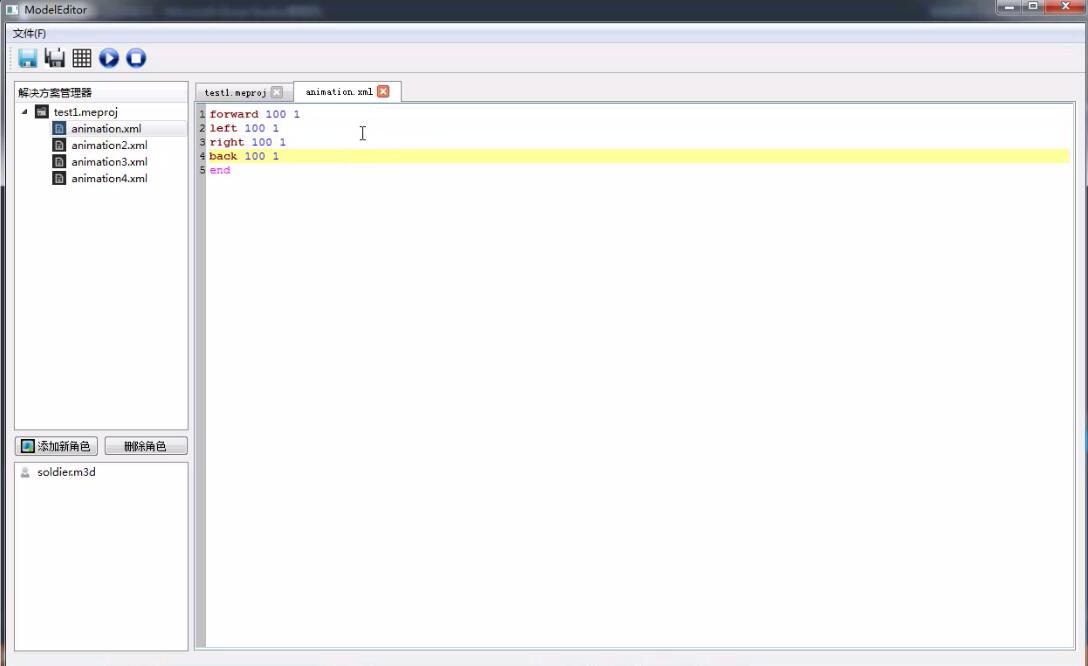
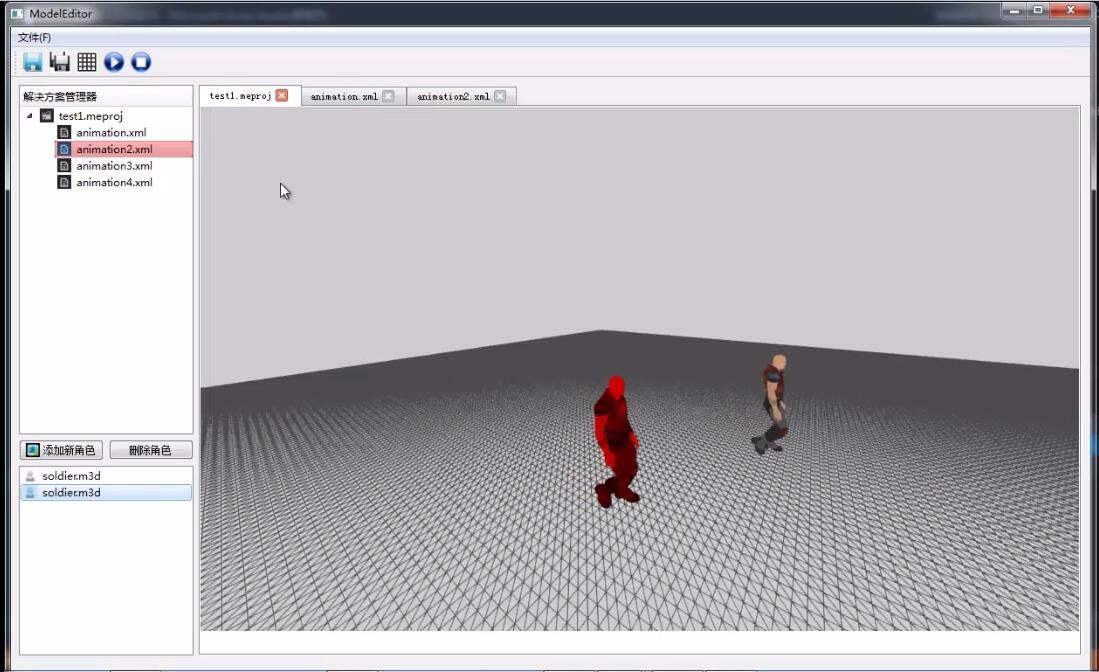
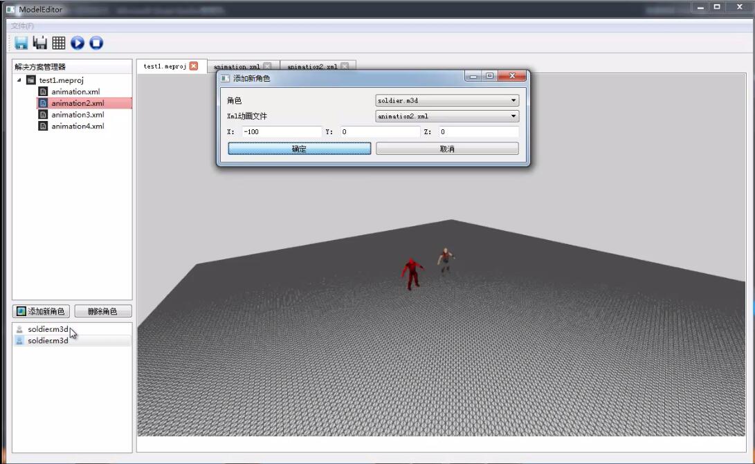
Animation Editor
This application allows user to generate their own movies based on real-time rendering. It reads
.objand.m3dinput files (.m3dfiles are the animation files provided by Introduction to 3D Game Programming with Directx 11)..meprojis a custom format used in our project. Users are able to control the motions of roles by XML files (the module of XML parser is still under development).
Visit this link to see my project on Github : https://github.com/immiao/ModelEditor.
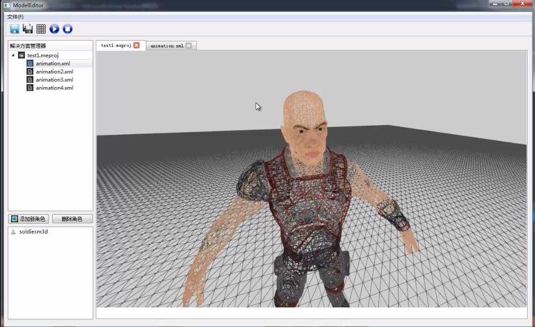
Character Animation
I implemented animated skinned meshes in my project.
- Bone Hierarchies
Many objects are composed of parts, with a parent-child relationship, where one or more child objects can move independently on their own (with possible physical motion constraints—e.g., human joints have a particular range of motion), but are also forced to move when their parent moves. For example, consider an arm divided into the parts: upper arm, forearm, and hand. The hand can rotate in isolation about its wrist joint; however, if the forearm rotates about its elbow joint, then the hand must rotate with it.
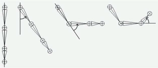
Hierarchy transforms; observe that the parent transformation of a bone influences itself and all of its children:
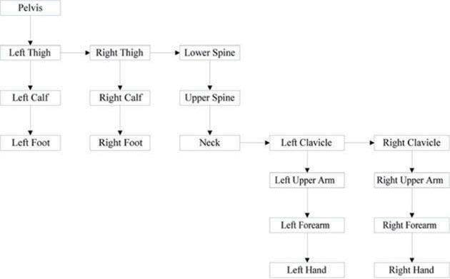
A more complex tree hierarchy to model a bipedal humanoid character. Down arrows represent “first child” relationships, and right arrows represent “sibling” relationships. For example, “Left Thigh,” “Right Thigh,” and “Lower Spine” are all children of the “Pelvis” bone:
- Bone Transformation
Let A2 be a matrix that transforms geometry from frame F2 into F1, let A1 be a matrix that transform geometry from frame F1 into F0, and let A0 be a matrix that transform geometry from frame F0 into W (world space). (We call Ai a to-parent matrix because it transforms geometry from a child’s coordinate system into its parent’s coordinate system.) Then, we can transform the ith object in the arm hierarchy into world space by the matrix Mi defined as:
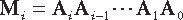
Because the coordinate systems exist in the same universe we can relate them, and therefore, transform from one to the other. In particular, we relate them by describing each bone’s coordinate system relative to its parent’s coordinate system. From that, we can construct a to-parent transformation matrix that transforms the geometry of a bone from its local coordinate system to its parent’s coordinate system. Once in the parent’s coordinate system, we can then transform by the parent’s to-parent matrix to transform to the grandparent’s coordinate system, and so on, until we have visited each ancestor’s coordinate system and finally reached the world space:
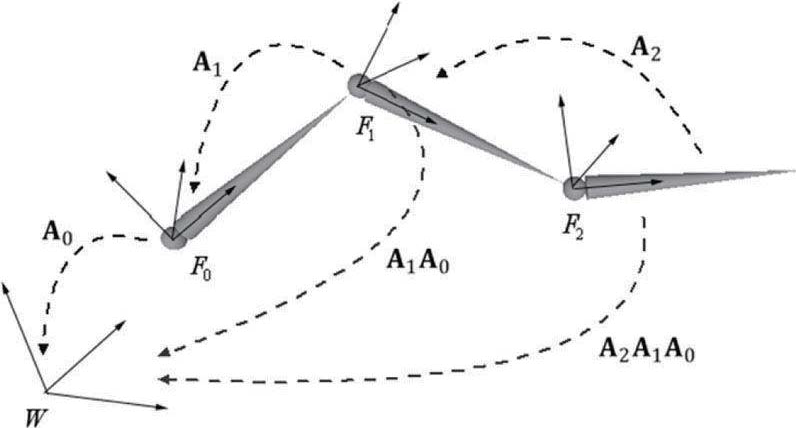
There is a small subtlety that comes from the fact that the vertices influenced by a bone are not relative to the coordinate system of the bone (they are relative to the bind space, which is the coordinate system the mesh was modeled in). So we first need to transform the vertices from bind space to the space of the bone that influences the vertices. A so-called offset transformation does this.
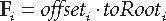
We now introduce a new transform, call it the final transform, which combines a bone’s offset transform with its toroot
transform. Mathematically, the final transformation matrix of the ith bone Fi is given by:
- Key Frame Interpolation
Interpolates the animations for each bone based on the current animation clip
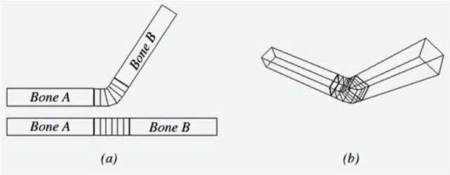
- Vertex Blending
The strategy of vertex blending is as follows. We have an underlying bone hierarchy, but the skin itself is one continuous mesh (i.e., we do not break the mesh up into parts to correspond with each bone and animate them individually). Moreover, one or more bones can influence a vertex of the skin; the net result being determined by a weighted average of the influencing bones’ final transforms (the weights are specified by an artist when the model is being made and saved to file). With this setup, a smooth transitional blend can be achieved at joints (which are typically
the troubled areas), thereby making the skin feel elastic.
- Core Code
Calculating the final transformation of vertex:
void D3DWidget::UpdateBoneTransformMatrix()
{
	if (!m_bReadFinish)
		return;
	qDebug() << "Updating : " << m_fTime;
	m_fTime += m_dt / 1000.0;
	// Interpolate
	for (UINT i = 0; i < m_animationClip.BoneAnimations.size(); i++)
	{
		std::vector<Keyframe> &rKeyframes = m_animationClip.BoneAnimations[i].Keyframes;

		if( m_fTime <= rKeyframes.front().TimePos )
		{
			XMVECTOR S = XMLoadFloat3(&rKeyframes.front().Scale);
			XMVECTOR P = XMLoadFloat3(&rKeyframes.front().Translation);
			XMVECTOR Q = XMLoadFloat4(&rKeyframes.front().RotationQuat);

			XMVECTOR zero = XMVectorSet(0.0f, 0.0f, 0.0f, 1.0f);
			//m_xmmBoneTransforms[i] = XMMatrixAffineTransformation(S, zero, Q, P);
			XMStoreFloat4x4(&m_xmmBoneTransforms[i], XMMatrixAffineTransformation(S, zero, Q, P));
		}
		else if( m_fTime >= rKeyframes.back().TimePos )
		{
			XMVECTOR S = XMLoadFloat3(&rKeyframes.back().Scale);
			XMVECTOR P = XMLoadFloat3(&rKeyframes.back().Translation);
			XMVECTOR Q = XMLoadFloat4(&rKeyframes.back().RotationQuat);

			XMVECTOR zero = XMVectorSet(0.0f, 0.0f, 0.0f, 1.0f);
			//m_xmmBoneTransforms[i] = XMMatrixAffineTransformation(S, zero, Q, P);
			XMStoreFloat4x4(&m_xmmBoneTransforms[i], XMMatrixAffineTransformation(S, zero, Q, P));
		}
		else
		{
			// pos in .m3d files are the position relative to its parent
			for(UINT j = 0; j < rKeyframes.size() - 1; ++j)
			{
				if( m_fTime >= rKeyframes[j].TimePos && m_fTime <= rKeyframes[j+1].TimePos )
				{
					float lerpPercent = (m_fTime - rKeyframes[j].TimePos) / (rKeyframes[j+1].TimePos - rKeyframes[j].TimePos);

					XMVECTOR s0 = XMLoadFloat3(&rKeyframes[j].Scale);
					XMVECTOR s1 = XMLoadFloat3(&rKeyframes[j+1].Scale);

					XMVECTOR p0 = XMLoadFloat3(&rKeyframes[j].Translation);
					XMVECTOR p1 = XMLoadFloat3(&rKeyframes[j+1].Translation);

					XMVECTOR q0 = XMLoadFloat4(&rKeyframes[j].RotationQuat);
					XMVECTOR q1 = XMLoadFloat4(&rKeyframes[j+1].RotationQuat);

					XMVECTOR S = XMVectorLerp(s0, s1, lerpPercent);
					XMVECTOR P = XMVectorLerp(p0, p1, lerpPercent);
					XMVECTOR Q = XMQuaternionSlerp(q0, q1, lerpPercent);

					XMVECTOR zero = XMVectorSet(0.0f, 0.0f, 0.0f, 1.0f);
					//m_xmmBoneTransforms[i] = XMMatrixAffineTransformation(S, zero, Q, P);

					XMStoreFloat4x4(&m_xmmBoneTransforms[i], XMMatrixAffineTransformation(S, zero, Q, P));
					break;
				}
			}
		}
	}

	// calculate final bone transformation
	std::vector<XMFLOAT4X4> toRootTransforms;
	toRootTransforms.resize(m_nBones);
	toRootTransforms[0] = m_xmmBoneTransforms[0];
	//XMMATRIX t = XMMatrixMultiply(m_xmmBoneTransforms[1], toRootTransforms[0]);
	for (UINT i = 1; i < m_nBones; i++)
	{
		int nParentIndex = m_vBoneParentIndex[i];
		//toRootTransforms[i] = XMMatrixMultiply(m_xmmBoneTransforms[i], toRootTransforms[nParentIndex]);
		//m_xmmFinalBoneTransforms[i] = XMMatrixMultiply(m_vBoneOffsets[i], toRootTransforms[i]);

		XMMATRIX toParent = XMLoadFloat4x4(&m_xmmBoneTransforms[i]);
		XMMATRIX parentToRoot = XMLoadFloat4x4(&toRootTransforms[nParentIndex]);

		XMMATRIX toRoot = XMMatrixMultiply(toParent, parentToRoot);

		XMStoreFloat4x4(&toRootTransforms[i], toRoot);
	}

	for(UINT i = 0; i < m_nBones; ++i)
	{
		XMMATRIX offset = XMLoadFloat4x4(&m_vBoneOffsets[i]);
		XMMATRIX toRoot = XMLoadFloat4x4(&toRootTransforms[i]);
		XMStoreFloat4x4(&m_xmmFinalBoneTransforms[i], XMMatrixMultiply(offset, toRoot));
	}

	if (m_fTime > m_animationClip.fEndTime)
		m_fTime = 0.0f;
}
Vertex blending in HLSL file:
VS_OUTPUT SkinnedVS(float3 Pos : POSITION, float4 Color : COLOR, float3 Weight : WEIGHT, uint4 BoneIndices : BONEINDICES,
					float2 Tex : TEXCOORD)
{
	VS_OUTPUT output = (VS_OUTPUT)0;

	float weights[4] = {0.0f, 0.0f, 0.0f, 0.0f};
	weights[0] = Weight.x;
	weights[1] = Weight.y;
	weights[2] = Weight.z;
	weights[3] = 1.0f - weights[0] - weights[1] - weights[2];

	float3 posL = float3(0.0f, 0.0f, 0.0f);
	for(int i = 0; i < 4; ++i)
	{
	    posL += weights[i]*mul(float4(Pos, 1.0f), gBoneTransforms[BoneIndices[i]]).xyz;
	}

	output.Pos = mul(float4(posL, 1.0f), gRoleWolrdViewProjMatrix);
	output.Color = Color;
	output.Tex = Tex;

	return output;
}
Results at Present Stage
The demo is uploaded on the following link : http://v.youku.com/v_show/id_XMTQ1OTkwNDg0NA==.html